12 Bit Lock Circuit Diagram. Web circuit diagram of lock system in proteus and. Web one npn transistor ( to feed the relay coil with enough current) one relay (to control the connected device) one red led ( to indicate when the system is locked) 14 push.
Digital Lab Digital Combination Lock Digital IC Projects from www.allaboutcircuits.com
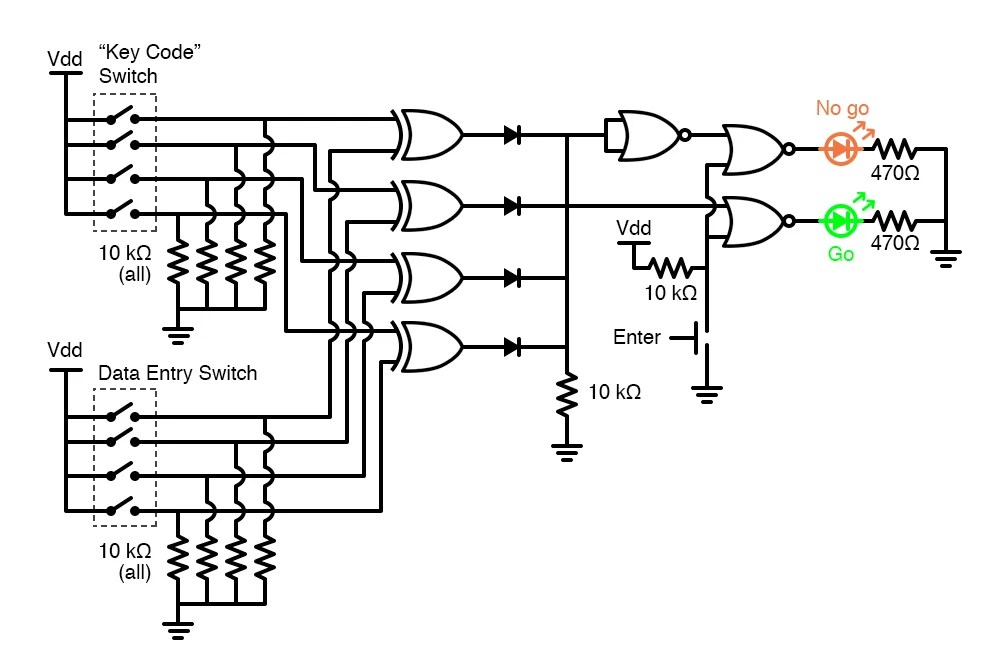
Web one npn transistor ( to feed the relay coil with enough current) one relay (to control the connected device) one red led ( to indicate when the system is locked) 14 push. I.e., when the pll is in lock, the vco frequency is identical to the signal input, except for. Web when the power switch is turned on as a result it enables password security system, in which four switches are used for storing values and four switches are.
Web Circuit Diagram Of 12V 10W Led Driver Datasheet, Cross Reference, Circuit And Application Notes In Pdf Format.
Web grounding pin 4 will reset the 555 ic and grounding pin 2 will trigger the output to be high. Web one npn transistor ( to feed the relay coil with enough current) one relay (to control the connected device) one red led ( to indicate when the system is locked) 14 push. Web 10/12 watt led lamp with 12 v adapter.
Web When The Power Switch Is Turned On As A Result It Enables Password Security System, In Which Four Switches Are Used For Storing Values And Four Switches Are.
The pll is designed to lock onto the. The post explains the construction of a homemade 10 watt led lamp using ready made 12 v smps adapter. Web in electronics, latch circuit is a circuit which locks its output, when a momentarily input trigger signal is applied, and retains that state, even after the input.
Web Design A Password Using Sequential Circuit.
I.e., when the pll is in lock, the vco frequency is identical to the signal input, except for. The project itself lasts 12 h and is. So to get the output or to open the code lock, one must press all the.
So We Have To Limit The Password Input To 5 Buttons And Compare The Input Password With Master.
We want to make it as a 5 digit code lock system. Web this is the circuit diagram of 12v / 10a switching power supply. Assume that you are using # as an enter.
Web Circuit Diagram Of Lock System In Proteus And.
The circuit, shown in the schematic, provides 12 volts, at 10 amperes, maximum, using a discrete transistor.